
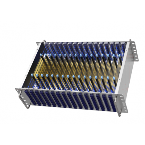
High-Density Optical Shuffle Solutions
Empowering 400G, 800G, and 1.6T Rail-Optimized GPU Trays with Direct Fiber Matrix Harnesses. Eliminate Cable Clutter, Reduce Insertion Loss, and Accelerate Cluster Deployment.
|
≤ 0.35 dB
Ultra-Low Insertion Loss
|
128 Fibers
Max Matrix Capacity
|
100% Zero
Wiring Mis-Match Errors
|
Multi-Rail
Mesh Fabric Alignment
|
1. What is an Optical Shuffle?
Definition & Core FunctionAn Optical Shuffle (also known as a fiber optical matrix harness or flex-printed shuffle module) is a pre-terminated, passive optical inter-connect device designed to route individual optical fiber channels between multi-fiber connectors in a specific, non-blocking crossover pattern. Instead of routing discrete fibers manually using patch cables, an optical shuffle packages the exact matrix arrangement into an ultra-thin, flex-printed ribbon assembly that fits cleanly inside 1U/2U server chassis and GPU trays. |
Why Shuffle is Needed for AI GPU TraysModern AI architectures (such as NVIDIA HGX/DGX or custom ASIC compute trays) utilize Rail-Optimized Networks. To ensure all GPUs can communicate simultaneously with minimum latency, each GPU transceiver's optical channels must be split and routed across 4 or 8 parallel network switch planes (rails). Without an optical shuffle, engineers would have to manually cross-connect hundreds of individual fiber pairs inside every GPU server, creating severe clutter, high installation failure rates, and choking cold airflow. |
2. How the Optical Shuffle Works
|
STAGE 1: INGRESS
Host GPU Transceivers
Multi-Transceiver Ports (OSFP/QSFP-DD) output multi-channel optical signals.
MPO Ingress Connectors
|
→ |
STAGE 2: FLEX MATRIX
Internal Flex-Printed Mesh
Fibers are woven inside a high-precision flex circuit tray in a non-blocking crossover matrix.
Cross-Connect Routing
|
→ |
STAGE 3: EGRESS
Network Switch Planes
Every Egress MPO trunk contains fiber channels from EVERY single host GPU in the chassis.
Multi-Rail Fabric Alignment
|
|
1. Mathematical Fiber Mapping
In an N x N optical shuffle, input connector A splits its M fibers so that each fiber maps directly to its corresponding output connector, creating a perfectly symmetrical mesh topology.
|
2. Bend-Insensitive Fiber Array
Utilizes ITU-T G.657.A2 single-mode fiber with ultra-tight bend tolerance (R = 7.5mm - 10mm), allowing fibers to criss-cross inside thin modules without signal loss.
|
3. APC Ferrule Alignment
Uses 8-degree Angled Physical Contact (APC) MPO ferrules to ensure return loss is ≥ 60 dB, preventing laser reflection back into high-speed transceivers.
|
3. Value of Optical Shuffle in GPU Trays
|
1. Airflow & Cooling
Replaces loose cable bundles with an ultra-thin flat flex printed ribbon. Preserves critical airflow pathways and prevents obstruction of liquid cooling manifolds.
|
2. Zero Mis-Match Risk
Internal matrix routing is 100% pre-terminated and factory tested. Eliminates human cabling errors across complex multi-rail switch topologies.
|
3. Link Budget
With insertion loss guaranteed ≤ 0.35 dB, the optical shuffle minimizes total channel attenuation, preserving precious decibels for external trunk cables.
|
4. 10x Faster Assembly
Reduces tray fiber installation time significantly. Enables rapid hot-swapping or field maintenance of GPU compute trays without disturbing adjacent fiber trunks.
|